Highly available, flexible torquemeters
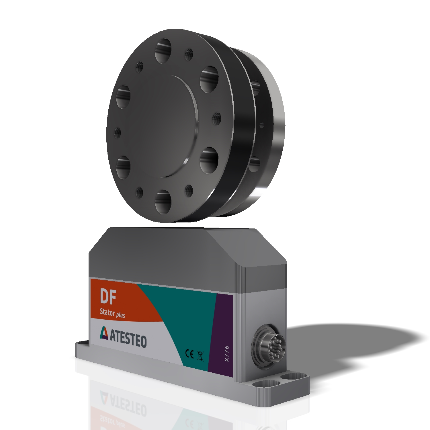
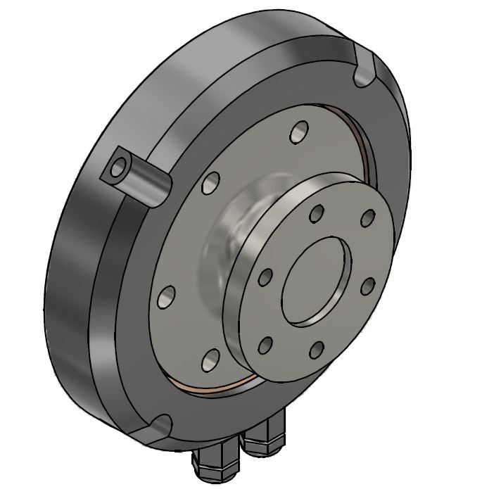
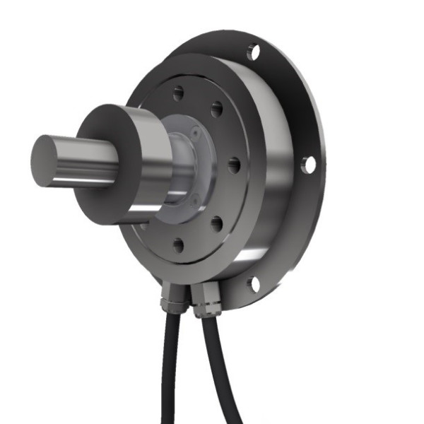
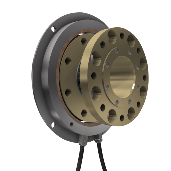
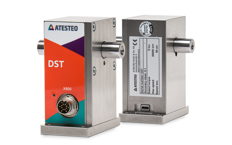
Torquemeters from ATESTEO measure the loads and torque arising in the drivetrain and supply measurement data for test bench control and analysis purposes. The high precision of standardised torquemeters and the flexibility in the design of highly specialised multi-channel torquemeters are an absolutely essential requirement for high test bench capacity utilisation.
Overview of our torquemeters
- 100 … 10,000 Nm
- 25,000 rpm
- Available as rotating and non-rotating torque sensors
- Space-saving due to extremely short construction
- Fully digital, 3 DMS amplifiers
- Standardised DIN flange sizes
- No stator ring
- 50 … 500.000 Nm
- 30.000 rpm
- Available as rotating and non-rotating torque sensors
- Optical data transmission (good EMV)
- Optional second torque range
- Integrated evaluation unit
- Optional optical/magnetic speed detection
- 50 … 200 Nm
- 40.000 rpm
- High speed torque transducer
- Optical data transmission (good EMV)
- 5 … 100 Nm
- 25.000 rpm
- Ideal for drag torque measurements
- Optical data transmission (good EMV)
- Optional second torque range
- 50 … 1.000 Nm
- 18.000 rpm
- Low mass inertia
- Increased speed stability
- Central bore for the mounting of a 2nd shaft
- 5 … 20 Nm
- 20.000 rpm
- Ideal for production lines / laboratory applications
- High accuracy due to one-sided bearing
- Compact and handy design / cost-effective
- 50 … 400 Nm
- 7,680 pulses/revolution
- Measurement steering wheel for installation in the vehicle
- Accuracy class ≤ ±0,1 %
- Extensive interfaces
State-of-the-art calibration facilities in the accredited ATESTEO calibration laboratory
Every ATESTEO torque transducer is calibrated in our own accredited calibration laboratory on state-of-the-art calibration equipment. The characteristic values (slopes) are determined on the professional equipment. Highly accurate and traceable measurement results are thus ensured. The DAkkS-accredited calibration laboratory also offers this service for third-party products.
Customised measurement shafts and torque measuring flanges
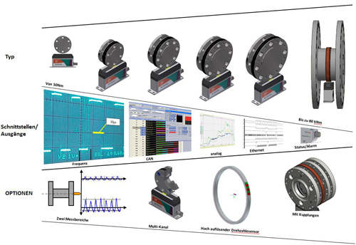
Besides standard torque measuring shafts, ATESTEO offers application-specific customer solutions from 1 Nm to 500 kNm. The sensor telemetry used is variable and can offer special options. Examples of customer solutions may include:
- Multi-channel capability such as torque and temperature
- Stationary measuring shafts – passive and active
- Measuring shafts made of titanium
- Different geometrical designs for stators and rotors
- Rotors with central bore to accommodate a shaft
- Customized measuring ranges
Individual request
Do you have specific requirements for your torque measuring shaft? Just send us an e-mail with your individual request. We will be pleased to advise you!
We are looking forward to your message!
FAQ – Frequently asked questions about torquemeters
The measurement uncertainty of torquemeters and torque transducers is determined from the accuracy values of the sensor and from the ambient conditions. The environmental conditions are, for example, temperatures or the influence of parasitic loads (lateral forces, bending moments). The parasitic loads must be measured, calculated, or estimated, depending on the requirement for the accuracy of the measurement uncertainty. The input data are ultimately converted into a measurement uncertainty value through a physical formula. ATESTEO is happy to assist with the calculation of the measurement uncertainty.
The DF series torquemeters offer a third measuring channel. This third measuring channel is called the overload channel. It can be used to measure torque values of up to 300% relative to the nominal torque (Mdn) of the sensor. Although the DF series torque sensors switches to an error mode when the valid measuring range (110% of Mdn) is exceeded, the torque can still be measured via the overload channel. This is particular helpful in analyzing undesired sequences (error in the automation sequence, problem in the test specimen/set-up, etc.).
Most of our ATESTEO torquemeters can be manufactured with customized nominal (rated) torque ranges. Because accuracy is relative to the nominal torque, this can improve accuracy in the system. However, it is possible that items with customized nominal torque ranges may result in increased costs or longer delivery times. Please contact us. We would be delighted to assist you.
We not only offer standard torquemeters, but on request, we will develop special solutions with our customers. Adapted nominal (rated) torque ranges are usually not a problem. In addition, we can build torquemeters (torque measuring shafts) that have a design customized to the equipment of the customer. Our design engineers discuss the customer requirements in detail and create proposed solutions. After the customer has approved the design, the components are produced in our own in-house mechanical workshop. We are also able to deliver customized solutions of the software and electronics. Please contact us; we would be pleased to assist you.
ATESTEO offers a second measuring range in many of its torquemeters. A separate amplifier section in the rotating measuring body allows smaller torque values to be measured more accurately than with the main amplifier section. This gives the torque measuring shaft a second physical measuring range (second nominal [rated] torque). The ratio between large and small measuring range (spread) is up to 1:5. So-called dual-range measuring flanges (dual-range torquemeters) offer the advantage of being able to measure test cycles with small and large torques. This can eliminate the need to exchange the torque measurement equipment. Only the switchover of the measuring range, a relief run, and a zero adjustment in the load-free state are necessary.
A torquemeter receives two sensitivity values after it has been calibrated. The sensitivity value is used to convert the raw measured value into a torque measured value. Therefore, the sensitivity value has the unit “Hz/Nm” or “digits/Nm”. One of the two sensitivitiy values converts the measured value of a positive loading direction (clockwise) into a torque value; the other sensitivity value converts the measured value of a negative loading direction (counterclockwise) into a torque value. To achieve maximum accuracy, both sensitivity values must be stored in the data recording system (measuring system or control system). If the data recording system only allows the input of one value, an averaged slope value can be calculated (with slight decreases in accuracy).
Various parameters of a torque measurement shaft have an influence on the accuracy of the measurement signal. These parameters are:
- Non-linearity, including hysteresis
- Relative standard deviation of repeatability
- Temperature influences on the zero point and the output signal
The accuracy class is determined by the worst of the named parameters. For example, if a torque transducer has the following accuracy values:
- Non-linearity, including hysteresis <= ±0.03%,
- Relative standard deviation of repeatability <= ±0.03%, and
- Temperature influences on the zero point and the output signal <= ±0.05%,
this results in an accuracy class of <=±0.05%.
The accuracy class always refers to the best output type of the sensor. For torque measuring shafts, this is usually the frequency output.
The percentage specification of the accuracy value refers to the nominal (rated) torque of the torque sensor. The accuracy class is not to be confused with the measurement error or uncertainty. The resulting measurement error is composed of the four parameters mentioned above and can be increased by parasitic loads (e.g., bending moment in the lateral direction) and environmental conditions. For an accurate error assessment, a measurement uncertainty analysis must be performed. ATESTEO is happy to provide support with this.
There are usually two variants of the F series and systems based on the F series. The “iS” variant has a housing below the ring stator in which the evaluation unit (electronics) is installed. In the “eS” variant, the evaluation unit is separated from the ring stator and installed in a separate housing. The “eS” variant can withstand slightly higher temperatures on the rotating shaft and requires less space in the shaft area. The “iS” variant does not require an additional holder for the evaluation unit and is less expensive.
For planning a facility, ATESTEO provides design data on its torquemeters. The data are dimensional drawings or 3D models (e.g., STEP files). Many torque sensors can be found around the clock on Traceparts.com. Dimensional drawings and 3D models can be downloaded from there. In any case, you can also request data directly from us. Just send us a request via email (equipment@atesteo.com).
Every ATESTEO torquemeter can send various status messages, such as error messages or alarms. This occurs, for example, through digital outputs or a detailed status word on the CAN bus. These signals permit the system to automatically monitor the status of the torquemeter. If errors or problems occur, deeper analyses can be performed using the configuration software. (See the question “How can I configure a torquemeter?”) Our service team would gladly assist you with this.
The product usually contains a factory calibration (see the text of the offer). As a result of the factory calibration, a test report is created in which the sensivity values of the torquemeter are recorded. The torquemeter can thus be operated. Optionally, a factory calibration certificate can be purchased. A factory calibration certificate provides further details on the calibration curve and the torquemeter characteristics. Furthermore, other calibration methods can optionally be used depending on the nominal (rated) torque. This includes, for instance, a calibration according to DIN 51309.
The calibration is applied to the main signal, the frequency output. Additional output types can be calibrated on request.
ATESTEO torque measuring technology is calibrated in our own in-house calibration laboratory.
ATESTEO torquemeters are already preconfigured on delivery and can be immediately used. Adjustment of the settings by the customer is only necessary if functions deviating from the standard are required (e.g., CAN bus). For adjusting settings, there is a configuration interface for each torquemeter. For the F series and series of F technology, a Windows software program (TCU-Config) is connected to the sensor via RS232. This makes configuration easy. The DF series of torque transducers provides a configuration web page. It can be easily accessed via Ethernet and a browser. Settings can be made using the intuitive web interface.
In a torque measuring shaft (torquemeter), torque causes the measuring body to twist; this twisting is initially measured with the aid of strain gauges. The strain gauges theoretically provide an infinite number of measured values per second. This raw signal is converted into a digital signal (frequency, data word) by electronic components. The conversion is achieved by internal high-frequency sampling. The outgoing measurement signal is now discrete in time and provides a limited number of measured values per second. The dynamics of a torquemeter define the maximum frequency that can be measured with the measuring signal via signal analysis.
Torquemeters are usually calibrated without a measuring system/data recording. This is why testing the measuring chain after receiving the torque sensor is a good idea. Torquemeters from ATESTEO offer the function of a test signal for this purpose. This signal can be activated via the configuration software. When the test signal is active, the sensor does not output a measurement value, but rather, a precisely defined signal. The definition of the signal can be found in the test report. The end of the measuring chain should be compared to this reference value.


